Use the Switching Capacity in Electrical Circuits for Current Protection
Key Takeaways
-
Power systems require short-circuit protection equipment or circuits to ensure safety and reliability.
-
When selecting a short-circuit current protection device or circuit, the switching capacity of the device needs to be known or determined.
-
There are multiple switching capacity values to consider in regulations and industry standards, and the correct value must be matched to the appropriate power system.
Microprocessor power consumption in many systems is a crucial design metric.
Components like power regulators, photovoltaics, reactive power circuits, or a FET might experience a short circuit at some point during operation. In some cases, such as in photovoltaics, this might be intentional under low-load or low-light conditions, causing the appearance of a ground fault where none exists. In power regulators, this value actually defines the maximum current it can supply under a zero load condition. In general, you don’t want a device to experience a short circuit as this causes large heat dissipation that destroys components. It is also a safety hazard, especially in power systems.
Component companies and power systems providers will often quote a particular value for the short-circuit current a device is expected to supply. This is important when selecting circuit protection devices as these need to detect and switch off short circuit currents when they occur. In power systems, we must determine an acceptable short circuit current limit that the system can tolerate. This limit needs to be matched to the switching capacity of an electrical circuit to ensure protection.
What is Switching Capacity in Electrical Circuits?
The switching capacity in electrical circuits, sometimes called the short-circuit switching capacity, defines the RMS current at a rated power factor cosφ and voltage at which a protection circuit can shut off a system. This value is supplied by manufacturers for specific overcurrent protection components and circuits, such as:
- Relays
- Fuses
- Circuit breakers
- BJT or MOSFET-based circuits
To ensure protection against equipment destruction or operator safety during a ground fault or short-circuit event, the chosen switching capacity must be greater than the expected short-circuit current. When we say “expected” short circuit current, this requires a comprehensive risk analysis of the maximum possible short circuit current and what could be expected given potential sources of faults in the system. The maximum and expected short circuit current, and the switching capacity, can be related as follows:
These limits are intended to ensure the system can be protected with a suitable overcurrent circuit or device but without destroying any equipment in the process. If this relation is not satisfied (e.g., switching capacity is too low), then some backup protection device or circuit should be placed, so the pair of devices/circuits have sufficient switching capacity.
Let’s look at the various short-circuit capacity definitions and where they apply in various power systems.
Types of Switching Capacities
The following types of switching capacities are codified in regulations, industry standards, or product specifications:
- Rated short-circuit making capacity: Some regulations state that this value must be in a specific ratio to the rated maximum short-circuit breaking capacity. Circuit protection device manufacturers must guarantee these values.
- Rated ultimate short-circuit breaking capacity: This value is defined for circuit breakers at an associated rated operational voltage in specific environmental conditions, defined in IEC 60947-2. The value must be at least as large as the prospective short-circuit current at the site of installation.
- Rated service short-circuit interrupting capacity: This value is also defined in IEC 60947-2 and is set lower than the ultimate breaking capacity. Setting this value as a minimum capacity limit ensures the protected equipment can remain serviceable after a protection device switches.
According to regulations, the rated short-circuit making capacity Icm is a quantity that must be in a particular ratio to the rated ultimate short-circuit breaking capacity Icu, which must be guaranteed by the device manufacturer.
Simulating Protection Measures
Reliability has historically been challenging to simulate quickly due to the inability to quickly see whether a protection device will effectively ensure power dissipation in components is low enough. SPICE simulations can be used to examine circuit behavior and power dissipation under short circuit events by connecting portions of the circuit directly to GND with a low-impedance element. As the impedance of the shorting element is brought to zero, you can examine how power dissipation in portions of the system changes and eventually brings the system to potential failure.
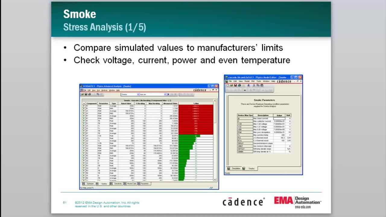
The newest reliability features in advanced SPICE simulations use “smoke analysis” to examine power dissipation in components and compare this to rated power dissipation from datasheets. By examining overstress levels during high current draw events, designers can determine points of failure in their systems and pinpoint the placement of short circuit current protection devices.
The switching capacity of a given circuit protection device is normally measured once it is built. However, it could be simulated, when based on a thermomechanical element, such as in a relay. These circuit protection devices can’t be evaluated using circuit simulations unless you already have data on the thermal/electrical behavior of portions of the system that can’t be modeled as standard circuit elements. This situation is where multiphysics simulations are needed to simulate more complex protection systems directly. These multiphysics simulations can be performed with a field solver integrating electrical analysis in your PCB layout and thermal analysis in mechanical elements.
You can better analyze and understand the switching capacity in electrical circuits with the complete set of system analysis tools from Cadence. Systems designers can assess reliability for their products and design appropriate circuit protection measures with integrated electrical and thermal simulations with a set of field solvers. The complete set of simulation features in powerful field solvers integrate with circuit design and PCB layout software, creating a complete systems design package for any application and level of complexity.
Subscribe to our newsletter for the latest updates. If you’re looking to learn more about how Cadence has the solution for you, talk to our team of experts.